[Table of Contents] |
[4. Tool encapsulation architecture] |
[6. Language processing] |
[Table of Contents] |
[4. Tool encapsulation architecture] |
[6. Language processing] |
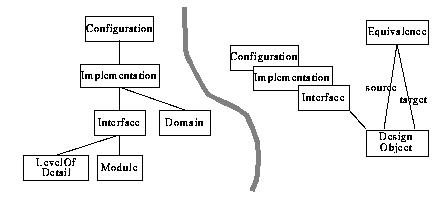 |
As an electronic design project proceeds, the specification of a designed module is refined stepwise; its interface evolves according to the levels of detail, each having a number of implementations in different domains. In our schema, a module represents an electronic system and aggregates a set of design objects that all describe the same electronic design. It forms the root of an inheritance tree of refined interfaces on various levels of detail which in turn have implementations in different domains. Interfaces are arranged in an inheritance tree where interfaces at low levels of detail are situated near the root and refined interfaces at high levels of detail can be found near the leaves. No dedicated relationship is reserved for the representation of this inheritance hierarchy. Rather, we use equivalence relationships between the interfaces in which the more abstract design objects assume the role of sources and the more refined design objects assume the role of targets (Figure 12).
type Date: INTEGER.
type Designer: STRING.
type Name: STRING.
type DesignObject = Date, Designer, Name.
According to our definition in the Introduction, a design object describes an electronic design. However, the type DesignObject defined here does not have an attribute to store a design description. The capability to be associated with design representation information is not represented explicitly in our schema. It is instead hard-coded into the framework module that provides design information management services to design tools through its programming interface.
type Class: STRING.
type Tool: STRING.
type Equivalence = source_DesignObject, target_DesignObject,
     Class, Tool.
Equivalence relationships are very versatile. Here, they are used to arrange interfaces in an inheritance tree.(2) It is not trivial and generally depends on the nature of the design domain to check if two design objects are equivalent with respect to a certain property (or, phrased differently: if the design objects belong to the same Equivalence Class). This somewhat vague notion of equivalence makes us introduce explicit equivalence relationships and not equivalence sets as proposed in [Katz 86]. Equivalence relationships are thought to be established by tools and not automatically by the DIM service. Equivalence transitivity is therefore introduced on a case-by-case basis by establishing explicit equivalence relationships between design objects and is not answered in advance by some global property of equivalence sets. Our use of equivalence relationships follows their use in the Nelsis schema as motivated in [vanderWolf 93], p. 88.
type LevelOfDetail:
     { `architecture', `algorithm', `functional_block', `logic', `circuit' }.
type Domain: { `functional', `structural', `physical' }.
type Module = Name.
type Interface = [DesignObject], LevelOfDetail, Module.
type Implementation = [DesignObject], Domain, Interface.
type Configuration = [DesignObject], Implementation.
Interfaces, implementations, and configurations are special design objects. As such, they inherit the capability to be associated with design representation information. They are arranged in a "static" (i.e., fixed by the schema) access hierarchy. Relatability ensures that whenever we want to create a configuration for a module, a corresponding implementation and interface have been defined first.
With this schema in mind, we regard a module as a set of design objects all describing the same electronic system from different view-points. The set of design objects is partitioned into three disjoint subsets according to the role the elements of each set play in the design description of an electronic system. Objects in the interface subset describe the appearance of an electronic system viewed from the outside. Each interface is related to a set of implementations that describe different approaches as to how this outside view is accomplished technically. An implementation itself may use components specified by another module. Which design description of either component exactly is used is described by design objects in the configuration subset. Again, there may be different alternative configurations for each implementation. This schema satisfies requirements R2, R3, and R5.
Projects allow to structure the global object pool so that design activities can be performed locally without effecting other projects. A production design environment would have to go even further and allow projects to be hierarchically composed of other projects. Each level of hierarchy introduces an additional level of privacy in which projects near the root of the hierarchy represent published designs and completed design libraries. In such a scenario, a designer uses a local project as a workspace in which he performs experimental design steps. He can use locally created objects as well as ones imported from further up in the project hierarchy. Once a set of design objects is stable, it is checked into a parent workspace and thus made public for other designers.
We will not introduce a formal schema for projects as this concept is not directly related to the problem of design tool encapsulation. An implementation nevertheless will have to add the concept of projects. Both our implementation bases offer projects either directly (Nelsis, [Dimes 93a], p. 13) or in the form of a hierarchy of workspaces (ObjectStore, [ObjectDesign 94], p. 15).
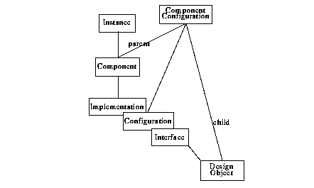
Components do not reference the used design object directly but via component configurations. Component configurations bind a component to a child design object (either of interface, implementation, or configuration) for a particular purpose. A configuration collects component configurations and may be used as the representative of a design object for a specific purpose like "Release 2", "Fast-CPU", or "Simulate-ALU" (Figure 13).
type DesignObject = Date, Designer, Name.
type Interface = [DesignObject], Module, LevelOfDetail.
type Implementation = [DesignObject], Interface, Domain.
These are the same definitions for DesignObject and its subtypes as in the previous section.
 |
type Constructor: STRING.
type Component = parent_Implementation, Name.
type Instance = Constructor, Component, Name.
Components establish hierarchy relationships between a parent implementation and another design object. We explicitly distinguish between components and instances to accommodate different uses of the information that is manageable by this schema. Design tools generally need the exact instantiation information with details about each instance. On the other hand, the encapsulation service only needs to know which design objects are used in which implementation. This information is represented by components.
type Info: STRING.
type Configuration = [DesignObject], Implementation.
type ComponentConfiguration =
     Component, child_DesignObject, Info, Configuration.
Component configurations establish the actual binding between a component and the design object that realizes it. This added level of indirection allows to manage a set of configurations as described above. With these definitions, we satisfy requirements R4 and R5.
Already more complex than a model for composition hierarchies without configurations, this model still does not allow to individually configure each occurrence of a sub-module in a composition hierarchy. If we wanted to model the configuration of individual occurrences as well, we would have to modify the type definitions as follows:
type Configurable = Name.
type ComponentConfiguration
     = Configurable, child_DesignObject,
     Info, Configuration.
type Component = [Configurable], parent_Implementation.
type Instance = [Configurable], Constructor, Component.
With this model, it is possible to individually configure each instance in an implementation. Although this amount of control may be desirable for purposes such as back-annotation, the introduction of additional components with different characteristics can still be applied when using the simpler model. In the sequel, we therefore choose the simpler model as depicted in Figure 13.
Figure 33 on page 176 depicts the composition hierarchy of the design description for the DP32 test bench circuit, including two configurations. The large diamonds in the figure represent configuration objects, the small diamonds represent component configurations. The links between configurations and component configurations are not shown. Rather, the two configurations and their respective component configurations are rendered in two different shades. As can be seen in this hierarchy graph, components never reference their child design objects directly but do so via component configurations.
A single configuration only references component configurations that configure components of a single parent implementation. Formally, the following assertion holds for all component configurations:
assert ComponentConfiguration its
  Configuration its Implementation
   == Component its Implementation
A single configuration may nevertheless configure components more than one level down the composition hierarchy. This is achieved by having component configurations specify a configuration, not an implementation or interface as child design object.
Consider, for example, the following excerpt from the configuration declaration for the DP32 test bench:
configuration dp32_rtl_test of dp32_test is
  for structure
    for cg: clock_gen
      use entity work.clock_gen (behaviour)
      generic map (Tpw => 8ns; Tps => 2ns);
    end for;
    for mem: memory
      use entity work.memory (behaviour);
    end for;
    for proc: dp32
      use entity work.dp32 (rtl);
      for rtl
        for all: reg_file_32_rrw
          use entity work.reg_file_32_rrw (behaviour);
        end for;
        for all: mux2
          use entity work.mux2 (behaviour);
        end for;
        -- more component configurations
      end for;
    end for;
   end for;
end dp32_rtl_test;
First, we note that in the configuration of dp32_test.structure the instances are configured individually. With our simplified model of component configurations we cannot in principle represent this fine "configuration granularity". As, however, each component is only instantiated once, we can safely replace the instance labels (cg, mem, proc) with all qualifiers without losing information. In more complex cases, the introduction of additional components would have been necessary.
In this example, a configuration for the register-transfer level implementation of the DP32 microprocessor is embedded in the configuration for the test bench circuit. Within this nested configuration, components are configured, this time directly using all qualifiers. The nesting of configurations resembles the logical nesting of sub-modules. Without losing information, we can unwind ("flatten") the configuration nesting by introducing explicit configuration declarations which are then referenced as children by the component configurations:
configuration dp32_rtl_test of dp32_test is
  for structure
    for all: clock_gen
      use entity work.clock_gen (behaviour)
        generic map (Tpw => 8ns; Tps => 2ns);
    end for;
    for all: memory
      use entity work.memory (behaviour);
    end for;
    for all: dp32
      use configuration work.dp32_rtl;
    end for;
   end for;
end dp32_rtl_test;

configuration dp32_rtl of dp32 is
  for rtl
    for all: reg_file_32_rrw
      use entity work.reg_file_32_rrw (behaviour);
    end for;
    for all: mux2
      use entity work.mux2 (behaviour);
    end for;
    -- more component configurations
  end for;
end dp32_rtl;
We can directly map this flattened configuration into an object graph according to our conceptual schema (Figure 14).
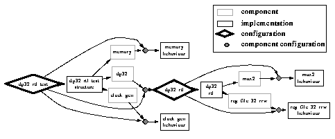 |
Although configuration dp32_rtl_test was our starting point, the configuration dp32_rtl originally nested within dp32_rtl_test now is a first class object of type Configuration and can be referenced from component configurations other than those contained in dp32_rtl_test. While simplifying the model, flattening nested configurations therefore simplifies design reuse.
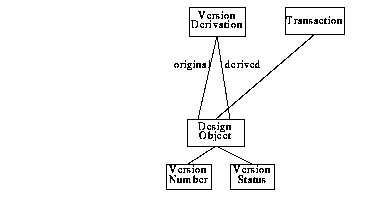 |
The relationships introduced in this schema are crucial to design management. However, we do not have to develop something new here as e.g. the schema of the Nelsis CAD Framework fits our needs well. We therefore take the following type definitions directly from the Nelsis schema [vanderWolf 93], only slightly extending the definition of DesignObject.
type Name: STRING.
type Date: INTEGER.
type Designer: STRING.
type Language: STRING.
type VersionNumber: INTEGER.
type VersionState: { `backup', `derived', `working', `actual' }.
type DesignObject =
     Date, Designer, Name, VersionNumber, VersionState.
type VersionDerivation = original_DesignObject, derived_DesignObject.
type CompletionMode = { `running', completed', `aborted' }.
type Tool: STRING.
type Transaction = Tool, CompletionMode.
type Module = Name, LastVersion.
The definition of attributes for version number and version state emphasizes the central role DesignObject plays in our schema. Design objects are the only entities that can be versioned. This property, of course, is inherited by its subtypes Interface, Implementation, and Configuration.
version derivation adds a further structuring mechanism to the set of design objects by allowing to relate a design object with a set of derived design objects and a derived design object with one or more originals. Note that in the case of more than one original a merge must have occurred to weed out potential incompatibilities introduced on the two branches. Design objects are versioned relative to a module. To uniquely identify objects within the module (other than by their object identifier), they are automatically assigned a version number on creation. In addition, a design object is assigned a version status for version selection in cases in which configurations are not used.
Design objects are involved in potentially long design transactions. Information about completed transactions and associated design objects is not simply deleted on transaction commit but is stored to render a complete design history.
Each design object is associated with a textual design representation in a selected design description language. In addition, it is also associated with the lexical context in the design file from which it originates and the offset in this context. In more complex situations, the design object itself may again play the role of a lexical context for some sub-ordinate design object (Figure 16). Figure 17 gives a schematic example; in Figure 18, lexical contexts are applied to a piece of VHDL description.
 |
 |
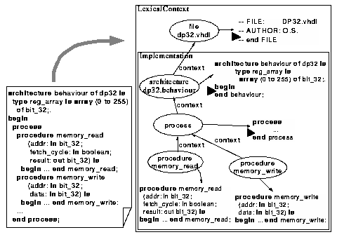 |
In more complex languages or if the design methodology dictates a more fine-grained management of design objects, a refinement of lexical contexts is called for. Lexical contexts only allow to manage the lexical structure of a hierarchy of contexts, basically by storing offsets into the context of a given design object. If the context itself is a DesignObject, it may be modified as such, invalidating the offsets of design objects lexically nested within it. An obvious solution to this problem is not to store a numeric offset with the child but rather to insert a special marker into the parent. This marker may be moved around freely, and, as long as it is not deleted, may be replaced by the text of the child on export. A disadvantage of this approach is that the parent context must be searched for markers to insert the text of children.
A further refinement is to actually retain the syntactical structure of the parent with respect to its children. An extension of the schema shown in Figure 16 accomplishes this (Figure 19):
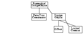 |
type LexicalContext = Language, Date, Designer, Name.
type DesignObject = [LexicalContext], LexicalContext, Offset.
type ParseTreeConstructor: STRING.
type SyntacticalDesignObject = [DesignObject], ParseTreeConstructor.
This schema answers two questions. (1) How are design objects embedded in their lexical context, and (2) how does the design object lexically or syntactically contain other design objects? Every design object is embedded in a lexical context. This results from the fact that we extract design objects from design files. There, the file (stripped of the actual representation of the design object) is the lexical context. There are two ways in which the design representation of textually nested design objects can be managed by the design information manager. In the simpler approach, a design object itself plays the role of lexical context for a set of embedded design objects as described above. In more complex scenarios, not the lexical but the syntactical structure of a design object is managed by the design information manager. A specialized form of DesignObject carries a parse tree constructor. A parse tree constructor is a piece of Tcl code that describes how to construct a parse tree from the values of a design object's attributes and those of related objects. In Section 6.5 on page 114 we will explain in detail what a parse tree constructor looks like and how it can be constructed largely automatically from a language specification.
Objects of aggregate types are accessed through object references. Such a reference may be the actual memory address of an object or a database identifier. Overloading in "C++" allows to handle both cases in a uniform and transparent way. Object references are only valid in the scope of a project. Before any other operation is invoked, a project handle has to be obtained by invoking the static member function
static dim_Project* dim_Project::open (string name, dim_OpenMode openMode);
OpenMode can either be read or update. For a given project, only a single project handle in update mode may be requested at any one time. Of course, multiple read handles may be requested. A project handle is released by a call to
void dim_Project::close (dim_CloseMode);
CloseMode may either be commit to request that all changes are to be made permanent or abort to discard all changes made with this project handle. The interface is schematically derived from our conceptual schema. Base types are mapped to the corresponding base types in "C++":
| Xplain base type | mapped to C++ type |
|---|---|
| INTEGER | int |
| REAL | double |
| STRING | char* |
For every Xplain definition
type BaseType: base-type.
there is a corresponding type definition in "C++":
typedef base-type BaseType;
The definition of an aggregate
type Aggregate = role_Component.
type Component = ... .
is mapped to two class definitions in "C++":
struct Aggregate {
  Component* role_component();
  void role_component (Component*);
};
struct Component {
  Set<Aggregate*> aggregates();
  ...
};
Please note that for each component there are two access functions, one to read a value and one to write a value. We do not map components directly to data members to have more control over the underlying implementation. For all practical purposes, a pair of access functions is equivalent to a data member. Access functions, however, are free to retrieve the actual data values from an underlying data manager or cache data values for greater efficiency.
Access functions automatically maintain consistency. In the above example, whenever a component is set for an aggregate, the aggregate is automatically inserted into the aggregate set in the component.
Access from a component to its aggregate is accomplished by set functions. The usual bunch of functions is provided to iterate through the elements in the set and to insert and delete members from the set. Only one function is needed to access the actual set.
A specialization in Xplain is mapped to class inheritance in "C++". For example, the following definition of a tree structure in Xplain
type Node = Value.
type InnerNode = [Node], parent_Node.
is mapped to the following "C++" classes:
struct InnerNode: public Node {
  Node* parent_node();
  void parent_node (Node*);
};
struct Node {
  Set<InnerNode*> inv_parent_nodes();
};
With these mappings it is possible to access all the objects managed by the design information manager. The only thing missing is a way to retrieve an initial object reference. This can be accomplished by accessing an object by its name with the following member functions of dim_Project:
Set<Module*> getModule (string moduleName);
Set<Interface*> getInterface (
  string moduleName, string interfaceName, string levelOfDetail);
Set<Implementation*> getImplementation (
  string moduleName, string interfaceName,
  string implementationName, string domain);
Set<Configuration*> getConfiguration (
  string moduleName, string interfaceName,
  string implementationName, string configurationName);
These functions return sets of design object references, because object names need not be unique within a project. The sets can be traversed to find the desired object.
dim_Interface* createInterface (
  string moduleName, string interfaceName,
  string language, string levelOfDetail);
dim_Implementation* createImplementation (
  string moduleName, string interfaceName, string implementationName,
  string language, string domain);
dim_Configuration* createConfiguration (
  string moduleName, string interfaceName,
  string implementationName, string configName);
If the named object does not yet exist, a new design object is created. If an object of this name already exists, a new version of it is created with version status working. In addition, lexical contexts are created with the function
dim_LexicalContext* createContext (
  string contextName, string language);
Normal contexts are not manipulated in an interactive design transaction. Rather, they are dynamically constructed from parse tree templates at the time of export (cf. Chapter 6 on page 103).
The following member functions of dim_Project open existing design objects:
dim_Interface* dim_Project::openInterface (Interface*, dim_OpenMode);
dim_Implementation* dim_Project::openImplementation (
  Implementation*, dim_OpenMode);
dim_Configuration* dim_Project::openConfiguration (
  Configuration*, dim_OpenMode);
These functions yield a handle for the corresponding object type, opened for read or update. After manipulations on any design object, the changes made have to be committed with the function
void dim_DesignObject::close (dim_CloseMode closeMode);
This call creates a new version that is derived from the original. The design object reference for a design object handle can be accessed by the function
DesignObject* dim_DesignObject::id();
The actual design data, in turn, are accessed through a stream-based interface:
dim_Stream* dim_DesignObject::openStream (
  string name, dim_OpenMode);
dim_Stream::read (int count);
dim_Stream::write (string buffer, int count);
void dimStream::close (dim_CloseMode);
Once a stream is opened, operations can be applied to get its size and to read and write its contents. To conclude, we have the following hierarchy of calls that reflects the transaction hierarchy needed to access the actual design data:
dim_Project::open();
    dim_Project::openDesignObject();
      dim_DesignObject::openStream();
        // stream access
      dim_Stream::close();
    dim_DesignObject::close();
dim_Project::close();
Set<dim_InstanceInfo*> dim_Configuration::getInstances
  (dim_BindingMode bindingMode);
returns a set of instance information structures. These are an abstraction of the instance type directly derived from the conceptual schema, conveniently hiding the component configurations from the programmer:
struct dim_InstanceInfo {
  string name;
  string constructor;
  DesignObject* child;
};
With binding mode static, for each instance, this structure references the child design object currently bound by the configuration. With binding mode dynamic, for each instance, an implementation object is selected:
void dim_Configuration::setInstances (Set<dim_InstanceInfo*>)
is used. Here, the set of instance information structures has to be constructed first and is passed to the function as a parameter.
Whereas the operations presented in Section 5.3.2 represent a low-level interface, the operations of Sections 5.3.3 and 5.3.4 work on lower levels of detail. Whenever a suitable, more abstract function is available to accomplish a certain task in design information management, it should be used for maximum protection. All three levels are open to the programmer, however, to provide a maximum in openness and flexibility. We will add a further, even more abstract level in Chapter 6 on page 103 where we describe the processing of design files in the encapsulation service.
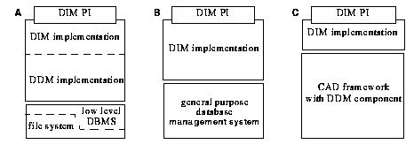 |
These capabilities can be found to varying degrees in database management systems based on each of the common data models. Object-oriented systems have the richest data model in terms of modelling power. As they are tailored towards engineering applications, many of them already support versioning as part of their data model. Support for large objects no longer is a privilege of object-oriented systems. Many relational database management systems today provide a similar feature as an extension to the classical set of column types. Navigational access is inherently weak in the relational model, whereas it is the standard access method in hierarchical and network models, which, on the other hand, have weak query facilities. Finally, concurrency control is available in all database models, but only the rich type system of the object-oriented model provides the necessary flexibility in access granularity. With all this, an object-oriented database system seems to have the best combination of features for our purposes.
Besides normal "C++", the programmer needs only a handful of additional procedures to
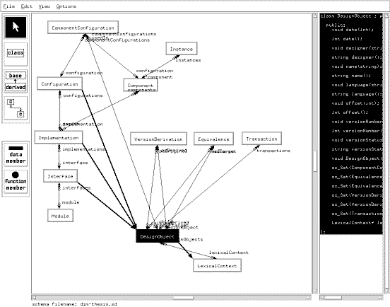 |
The classes DesignObject and Module are defined as sub-class of the system-defined class os_configuration. A configuration in ObjectStore defines a set of objects that evolve together. We use configurations together with hierarchical workspaces to implement automatic versioning. When an os_configuration is checked out from the global workspace into the project workspace associated with a project handle, a new version of it is created in the project workspace that is only visible there. Only on check-in this version is frozen and made visible to other users of the same project. Access by name through the functions getModule, getInterface, getImplementation, getConfiguration is supported by maintaining the class extents of the respective classes as database roots.
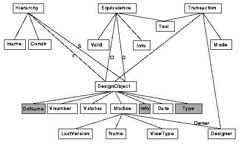 |
Every design object is uniquely defined by its version number and its module. Additional attributes of design objects hold its version status (either backup, actual, working, or derived), and its modification date. A working version represents work-in-progress and is overridden when a new version is checked in. Only one working version may exist in a module at any one time. When the designer is confident about the maturity of the working version, she can freeze and publish it by changing its version status to actual. Nelsis assumes an actual version to be frozen and published. This version is used automatically for constructing composition hierarchies if no other version is explicitly selected. It is protected against overriding by the system. When a new working version is designated as actual, the old actual version becomes a backup. Backup versions are retained to maintain a complete design history. In addition, versions may be deliberately designated as being derived from another design object to protect them against overwrite. There may be many backup and derived versions in a module.
Design objects may be related by the many-to-many relationships Hierarchy and Equivalence. Transactions record design transactions performed on a particular design object and thus allows to retrieve its history. Equivalences are used for many purposes, one not so obvious being a version derivation relationship. Other uses include relating design objects from different view types. Here it is anticipated that the actual validation of the equivalence is performed by some tool such as a design rule checker, a circuit extractor, or a synthesis tool. We only describe the core of the complete Nelsis schema as far as it directly relates to our implementation of design information management. The production schema contains many more types for trans-project references and design flow management. A more thorough discussion of all the features of the Nelsis schema can be found in [vanderWolf 93].
The DIM type Module is mapped to a set of Nelsis Modules that all have the same name, but different values of the ViewType attribute. The function getModule
Set<Module*> getModule (string moduleName);
is implemented with the query
get Module where Name == `$moduleName'(3)
The DIM type Interface is mapped to the Nelsis type Module. As a module in Nelsis cannot be associated with design data directly, a single design object in each module is designated as the container for the interface description.
The function getInterface
Set<Interface*> getInterface (
  string moduleName, string interfaceName, string levelOfDetail);
is implemented with the query
get DesignObject where
  Module its Name == `$moduleName' and
  Name == `$interfaceName' and
  Type == `interface'
The DIM type Implementation is mapped to the Nelsis type DesignObject. The function getImplementation
Set<Implementation*> getImplementation (
  string moduleName, string interfaceName,
  string implementationName);
is implemented by retrieving an interface design object with the function getInterface, storing its module as module, and then issuing the query
get DesignObject where
  Module == `$module' and
  Name == `$implementationName' and
  Type == `implementation'
The DIM type Configuration is also mapped to the Nelsis type DesignObject. The function getConfiguration
Set<Configuration*> getConfiguration (
  string moduleName, string interfaceName,
  string implementationName, string configurationName);
is implemented similar to getImplementation by retrieving an interface design object with the function getInterface, storing its module as module, and then issuing the query
get DesignObject where
  Module == `$module' and
  Name == `$implementationName' and
  Info == `$configurationName' and
  Type == `configuration'
The DIM type LexicalContext has to be modelled as Nelsis type DesignObject because it is associated with design data. For each lexical context a new module and in it a single design object is created. The module has view type `$language-context'. Syntactical contexts are not mapped to Nelsis. Instead, they are dynamically constructed on export from a parse tree template and attribute values of the participating design objects.
The other types of the DIM schema are mapped as follows. Instances are not represented at all. For the export of design objects as files it is irrelevant how many and which exact instances are used by a particular implementation as long as the child design object to be exported is known. ComponentConfigurations are identified with the Hierarchy objects a design object that implements a configuration is involved in. VersionDerivation is handled automatically by Nelsis and is mapped to Nelsis Equivalence relationships. Transaction is also handled automatically.
dim_Interface* createInterface (
  string moduleName, string interfaceName,
  string language, string levelOfDetail);
first tries to create a new module using the query
insert Module its
  Name = `$moduleName',
  Designer = `$env(USER)',
  ViewType = `$language-$levelOfDetail'
The variable language here denotes the hardware description language used for the interface. The variable env is a global associative array in Tcl that gives access to environment variables. An error is signalled when such a module already exists. Then, a design object do in this module is opened for update. As Nelsis does not know about the additional attributes on DesignObject in the Nelsis schema, they have to be set manually:
update DesignObject `$do' its
  Name = `$interfaceName',
  Info = `$language',
  Type = `interface'
Note that with this mapping approach, interfaces cannot be versioned. Versioning on interfaces has to be simulated by creating them in separate DIM modules. The function dim_Project::createImplementation
dim_Implementation* createImplementation (
  string moduleName, string interfaceName, string implementationName,
  string language, string domain);
inserts a new implementation design object into the module that contains the associated interface object. Versioning is done automatically by Nelsis. The additional attributes again have to be updated manually:
update DesignObject `$do' its
  Name = `$implementationName',
  Info = `$language',
  Type = `implementation'
An implementation design object also serves as its own first configuration. This accounts for the fact that Nelsis does not support explicit configurations. The function dim_Project::createConfiguration
dim_Configuration* createConfiguration (
  string moduleName, string interfaceName,
  string implementationName, string configName);
works similar to dim_Project::createImplementation. The additional attributes are updated as follows:
update DesignObject `$do' its
  Name = `$implementationName',
  Info = `configurationName',
  Type = `configuration'
The function dim_Configuration::getInstances
Set<dim_InstanceInfo*> dim_Configuration::getInstances
  (dim_BindingMode bindingMode);
with binding mode dynamic simply issues the query
get Hierarchy its Name, Constructor, Son-DesignObject,
  Son-DesignObject its Type
to create a set of instance information structures. For binding mode static, the function starts off with the same query. According to the type of the child design object, the appropriate implementation design objects have to be selected as described in Section 5.3.
Whenever a design hierarchy is used by a tool that needs a static binding (e.g. a simulator), hierarchies with binding mode dynamic are treated separately. The install operation is used to replace the child design object with empty implementation part with a design object from the same module, i.e. one with a "compatible", possibly refined interface. The actual version is chosen if one exists, otherwise the design object with the highest version number will be used.
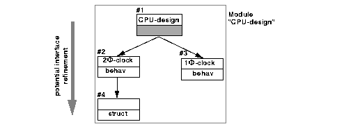
Using this approach, a module in Nelsis does not represent a single interface but rather a set of implementations with similar interfaces (Figure 23). Implementations with incompatible interfaces are collected in separate modules, related to each other by equivalence relationships. While this approach is quite valid on its own, it does not fit equally well into the Nelsis philosophy of identifying a module by its name and view type. Many dissimilar design objects are collected within a single module. It is also not possible to support an actual version for each interface as Nelsis only allows one actual design object per module.
 |
A configuration management approach more powerful than the one found in e.g. the Nelsis CAD Framework was called for by the need to represent VHDL configurations in the DIM service. Also, Nelsis does not distinguish between interface and implementation, a prerequisite for top-down design.
In [CFI-FAR 93], CFI outlines the concept of references that are bound by configurations. Although this document does not describe an existing, working system, the concepts described form the basis for existing frameworks such as the JESSI Common Framework. We have transcribed the intuitive drawings from [CFI-FAR 93], "Data Management Information Model" and "Version Information Model", into the Xplain notation to be able to compare it to our conceptual schema (Figure 24). This transcription can only serve as a coarse approximation of the original intent of the authors of the CFI document. Although no cardinalities were attached to relationships in the informal CFI schema, the appearance of an Xplain schema is largely determined by the different cardinalities so cardinalities had to be guessed from the textual description. Also, type Binding was only described textually.
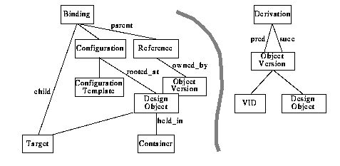 |
The first observation is that this schema does not distinguish interface and implementation of a design object from each other. This may be due to the fact that more domain specific schemas are intended to augment this schema with domain specific specializations of the types defined here. The overall structure of the types Configuration/Binding/Reference seems to resemble our types Configuration/ComponentConfiguration/Component as depicted in Figure 13 on page 72. However, CFI does not restrict their retargetable Reference to composition hierarchies. The binding policy we have implemented globally in the programming interface (see Section 5.3.4 on page 87) is bound to the type ConfigurationTemplate in the CFI schema so that in principle different binding strategies can be used. We have no information as to whether such a system has been implemented yet.
[Table of Contents] |
[4. Tool encapsulation architecture] |
[Top of Chapter] |
[6. Language processing] |