[Table of Contents]

[Stellingen, english version]

[2. Integration]

1. Introduction

1.1 Overview

Today, there is a growing gap between IC fabrication technology and the capability of Electronic Design Automation (EDA) Systems to help design electronic systems. Many design tasks on gate and register-transfer levels can be accomplished by standard tools offered by the big EDA system vendors. On higher levels, however, tool development is still very vivid. The largest productivity improvements are to be expected for design on algorithmic and architectural levels. Such "advanced" solutions often cannot be bought off-the-shelf from the big EDA system vendors but have to be bought from innovative niche vendors or even have to be home-grown.

Innovative electronic design requires close cooperation between system engineers, system architects and IC designers. Design environments with powerful facilities for design information management and browsing are needed to close the communication gap between these people [DeMan 92]. In this thesis we describe how to build an integrated environment for automated electronic design, based on the following observations:

  1. Integrated design environments are constructed from framework components and design tools. While design tools perform the actual design steps, i.e. they transform design descriptions, framework components provide an operating environment for design tools and a working environment for designers.
  2. The design environment should be open to combine the best available design tools for each design task. This implies that the design tools used have no built-in knowledge about the other tools and framework components in the design environment. They have to rely on standards to accept control input and to transfer design descriptions to and from the other constituents of the design environment.
  3. Although it is attractive to use procedural interfaces to interface design tools to each other and to the framework components, none of the proposed solutions is mature enough or generally accepted by tool vendors as the primary design data interface of their choice to use with their tools. For example, the CFI Design Representation Programming Interface [CFI-DRPI 93] is sometimes supported in addition to a tool's native design file interface. No example is known to the author where such a standard programming interface is offered as the sole design data interface for a production design tool.
  4. Instead, production design tools use (standard) hardware description languages as their primary interface to design descriptions. They transfer input and output data in design files. A design file may contain batches of arbitrary numbers of "design units".
  5. Design units are the natural building blocks of an electronic design. Sometimes they represent actual physical devices that are used to assemble a design, sometimes they are logical abstractions that only exist to introduce structure and thus make a design manageable by a team of designers. When designers work on a design, they manipulate design units and their relationships to each other. Design units appear in schematic or block diagrams, are used in part lists, are combined to form more complex design units, and evolve over time. The habit to store and transport design units in files is imposed by the file system centred user view offered by contemporary operating systems.
Traditionally, research on design tool integration has focused on providing procedural interfaces to tightly integrate design tools into a design environment [Hunzelmann 92]. Unfortunately, little of this work has found its way to everyday design reality. Instead, state-of-the-art design tools interface to the outside world by means of standard design description languages like VHDL or Verilog. The obvious solution to integrate file-based design tools with framework components is to have the framework manage design files. This approach is called encapsulation and implies that the actual design tool is encapsulated in a wrapper that performs framework-specific house-keeping like setting up an execution environment, importing and exporting design files from a protected database managed by the framework, and communicating with the framework user interface.

While everybody does it, file-based encapsulation is generally considered to be a bad thing for the following reasons:

  1. There is considerable overhead in having each tool parse and analyse a textual design description. This holds even more for complex languages like VHDL.
  2. Simple encapsulation assumes that all necessary design files can be provided to a design tool before its start. All results produced by a tool are determined by the way it is invoked. Interactive tools are different in that they allow a designer to manipulate additional design files during the tool run.
  3. Designers do not work on their designs in terms of design files but rather in terms of design units and their relationships. When managing complete files, a framework can scarcely help the designer in keeping track of relationships between design units. There seem to be two completely different spheres:
    (a) tightly integrated design tools, working on individual design units, and
    (b) encapsulated tools working on files. Sophisticated graphical browsers and query interfaces help designers to keep track of design units and their relationships. Nothing but directory browsers are usable on design files.
Our goal is to provide a new framework service for design tool encapsulation that bridges the mismatch between designers' notions of design units and the design files manipulated by design tools. Our solution is to analyse a design file on input into the framework database and to split it into a set of text chunks each describing an individual design unit. On export, these text chunks may be recombined in flexible ways to form a complete design file which can be fed into a design tool. Thus, the framework can manage individual design units, establish relationships between them and recombine them any way the designer chooses.

We do not attempt to overcome the overhead of design file parsing. Design units are still transported to and from design tools using files as carriers. However, the designer has finer and more flexible control over the selection of design units to be fed to a design tool. Design files are dynamically created from a selected set of design units to be manipulated during a particular design tool run. Hence, the design files fed to a design tool need only contain the necessary design units and thus can be smaller.

We have chosen the following approach to design tool encapsulation:

  1. To define the architecture of a new framework service and integrate it into a commonly accepted reference architecture [CFI-FAR 93]. The new service facilitates the mapping between design units and their relationships carried in design files and corresponding objects and relationships managed by the framework. It does so by performing design file analysis and construction. It further starts and controls design tools, communicates with them, and interprets their outputs. The proposed framework service is constructed around a scripting engine [Ousterhout 90] to provide end-user programmability.
  2. To formally define a conceptual schema for objects and relationships managed by the framework. Existing framework schemas are either not formally defined [Wagner 91], or do not provide the required flexibility [Kathöfer 92], [Dimes 93a]. Defining a completely new schema has the advantage of being a clean concept and being portable across different frameworks.
  3. To provide a toolkit for processing design files and mapping design units found therein to objects managed by the framework. Rather than hand-crafting language processors for important design description languages like VHDL and Verilog, we are of the opinion that a general toolkit provides more flexibility to the environment builder. Thus, the framework is not restricted to supporting a limited set of languages. Support for different languages or dialects of existing languages can easily be constructed.
We describe a prototype design environment that was implemented using this approach. The portability of the conceptual schema was demonstrated by implementing it on a CAD Framework as well as on an object-oriented database. A set of VHDL-based, state-of-the-art synthesis design tools was encapsulated using automatically generated language processors and a small number of scripts.

1.2 Design complexity

Electronic designs are complex. Several management techniques have been implemented in integrated design environments over the years to reduce this inherent complexity. Some techniques are unique to electronic design, others were borrowed from software engineering and related disciplines. We assume the following property of electronic designs:

Property:
All aspects of an electronic design pertinent to its construction, test, and application are formally defined in a set of design descriptions.

1.2.1 Views

One approach to tackle complexity is to organize the various aspects of an evolving electronic design into the categories domain and level of detail. Collectively, these two categories are often referred to as the view dimension of electronic design [vdHamer 94]. Three, occasionally four domains are distinguished for electronic design descriptions (Figure 1, Walker and Thomas [Thomas 83], [Walker 85], based on earlier work by Gajski and Kuhn [Gajski 83]). The four domains are characterized by the primitives used in design descriptions:


Figure 1.
The Y-Chart by Walker and Thomas, based on work by Gajski and Kuhn. Every design description has a domain (behavioural, structural, or physical) and a level of detail(1). Synthesis design steps are depicted by trajectories taken from one of the outer circles (abstract - low detail) towards the centre (specific - high detail). The diagram shows an example synthesis trajectory from the design methodology implemented in the CMU design automation system. Analysis steps (extraction, simulation) derive an abstract description from a more specific one.

The distinction between domains and levels of detail leads to the following

Definition:
A design object describes an electronic design in a particular domain and on a particular level of detail, as it exists at a particular point in time. The set of all design objects for a single electronic design is referred to as a module. A design object is uniquely identified by the tuple (module, domain, level of detail, version).

Synthesis steps transform design objects from a low level of detail in the behavioural domain to higher levels of detail in the structural or physical domains (Figure 1). Synthesis steps are one-to-many transformations, e.g. there are a number of possible sets of ALUs, MUXs, registers, etc. (structural domain) implementing a set of register transfers (behavioural domain). Exploring the design space means to construct a compound design object from any of a number of alternative sets of design objects from the behavioural, structural, or physical domains. This implies that although a design object is associated with a specific domain, it may itself be composed of design objects from different domains. Quite commonly, alternative decompositions of a design object are used for different domains and different levels of detail.

1.2.2 Abstraction

Another approach to handle complexity is abstraction, accomplished by the distinction of interface and implementation. This particular notion of abstraction was made popular by structured programming in software engineering. The objective for abstraction is information hiding and simplification of reuse. When using a module, the designer should only have to deal with its well-defined interfaces but not with the intricacies of an underlying implementation. It must even be possible to select a different implementation for a given interface, e.g. one on a higher level of detail.

Definition:
The set of design objects defined for a module is partitioned into disjoint subsets, referred to as interfaces. Each design object is placed into exactly one of these interface sets and is associated with exactly one implementation. Whereas the interface specifies a design object as seen from the outside, its implementation defines its hierarchical decomposition.

An electronic module realizes a specific electrical behaviour. This behaviour can only be controlled and observed through its interface. An interface has a number of interface elements which are used to interface the module with the outside world. The behaviour on a very low level of detail (i.e. on architectural level) is reflected in a core interface. The more refined the specification becomes on higher levels of detail, the more the data types for interface elements are refined [Wagner 91]. Table 1 gives some typical data types for interface elements on different levels of detail in the behavioural domain.


Table 1.
Typical data types for interface elements on different levels of detail in the behavioural domain
Level of detail Typical data types for
interface elements
architecture Ethernet, RS-232, SBus
algorithm integer, float, array, record
functional block bit, bus, bundle
logic bit_7
transistors 0..3 Volt

In addition to data type refinement, there may be completely new interface elements on higher levels of detail:


Table 2.
Interface elements in different domains
Domain Interface primitives
behavioural variables
structural signal ports
physical geometries

Moving to a different domain, however, will almost certainly change the interface, simply because the interface primitives are different (Table 2). Especially design objects in the physical domain have interfaces that are non-isomorphic with those in the behavioural and structural domains due to the radically different kind of information represented in this domain.
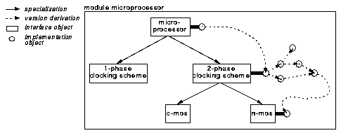

Figure 2.
Inheritance tree of compatible interfaces. All interfaces belong to the same module and thus are functionally equivalent. Interfaces are linked to implementations which in turn are related by version derivation relationships.

Interfaces in one module are related to each other in an inheritance tree each node of which is a refinement of its parent (Figure 2). It may add or refine interface elements defined by its parent. Arranging interfaces in inheritance trees ensures that interfaces in a module are compatible to each other in the sense that refined interfaces can only add new interface elements or refine existing ones but can not introduce incompatible changes such as deleting interface elements or introducing incompatible type changes. An interface may be associated with a graph of implementations, each of which defines an exact realization of behaviour, structure, or geometry.

1.2.3 Hierarchy

The third approach to handle complexity is hierarchical decomposition. In the behavioural domain, the implementation of a procedure may recursively contain procedure calls. In the structural and physical domains, the implementation of a compound module may contain sub-modules.

Definition:
The implementation of a module may make use of other modules. We call such a module a compound module; the used modules are referred to as components. A component may appear more than once in the implementation of a compound module. The individual manifestations are called instances.

There are two important observations related to hierarchical composition:

Property:
A module used as component typically is itself a compound module, constructed from instances of more primitive modules. Instances two or more levels down a composition hierarchy are sometimes called occurrences. It is important to keep track of occurrences to completely specify the hierarchical decomposition of a module.

Property:
A design object may be hierarchically decomposed into design objects on different levels of detail. It is important to note that the decompositions of design objects in a single module may be non-isomorphic, i.e. there is no one-to-one mapping between the decomposition structures.

1.3 Design methodology

We assume a design methodology that proceeds basically top-down. Views, abstraction and hierarchical decomposition are used to reduce design complexity. Design starts with a behavioural description of a design on a low level of detail. This description defines the top-level behaviour of the design in terms of programming language constructs like communicating processes, (recursive) procedures, loops, abstract data types, or variables. The design is either self-contained or has an interface defined in terms of high-level data types. The design implementation is then partitioned into a hierarchy of functional blocks, each of which is again defined by its behaviour.

Property:
In general, interfaces are defined before their implementations.

First, the interface of each functional block is defined and only then are the individual block implementations realized. The high-level behavioural design description is then stepwise transformed into a physical description on circuit level. A number of commercial and research synthesis tools exist to automatically perform these transformations on functional block level, logic and circuit levels [Walker 91]. Apart from synthesis tools, there are extraction and simulation tools that validate design results and allow to compare the behaviour of implementations in different domains and on different levels of detail (cf. for example [Greiner 93]).

While exploring design alternatives for a complex module, the selection of a specific implementation of a component needs to be flexible. On the other hand, once a module is released to a customer or other developers, its composition must be well-defined and fixed. We use configurations to provide this flexibility.

Definition:
A configuration is associated with an implementation of a particular module. It defines a tree of design objects and subordinate configurations by recursively selecting interfaces, implementations or configurations of components used in this implementation.

During early design stages, it is appropriate to always select a working implementation of a component by some default selection rule. Depending on the design task, however, the explicit selection of implementations from different levels of detail and from different domains may be more appropriate. Or, the designer of a module used as component in other modules may designate a selected implementation as the default, leaving it up to the designers of compound modules to select other implementations for special purposes. During simulation, for example, only questionable components need to be simulated to full detail. Other components may just be simulated behaviourally at a low level of detail. Designers will want to build a specific configuration of a design object for different design tasks and store them in the framework database alongside the actual design objects.

1.4 Design description languages

In 1987, the hardware description language VHDL was standardized by IEEE [VHDL 87] and has become a driving force in EDA interoperability today ([Carlson 92], [Heusinger 93]). All major EDA tool vendors support VHDL descriptions as input for synthesis and simulation tools and as result format on various levels of detail in the behavioural and structural domains. Apart from VHDL, there are other mature languages like EDIF [EDIF 88] that are in constant use in electronic design practice, especially for representing circuit schematics and netlists. Yet other formats like CIF of GDSII are used for representing design in the physical domain.

On the other hand, after five years in existence, the Design Representation Programming Interface [CFI-DRPI 93] defined by the CAD Framework Initiative (CFI), the dominant standardization body in the field, is still restricted to representing electrical connectivity data. Electrical connectivity deals with structural aspects of a design on functional block, logic, and circuit levels. As can be seen in the Y-Chart (Figure 1 on page 8), it does not cover all aspects necessary to describe a complete electronic design. To conclude, it is to be expected that language-based design tool interoperability will be common-place for some more years.

1.5 Design environments

Successful design of a complex electronic system in a team of designers not only requires the reliable management of design objects themselves but also the maintenance of a complex web of structural information (relationships and annotations) about the design objects. Relationships between design objects are used to build composition hierarchies, to associate derived design versions with their originals, or to relate design objects that are functionally or otherwise equivalent. Several researchers ([Batory 85], [Katz 86], [Biliris 89], [Bredenfeld 90], [Wagner 91], [Brielmann 92]) have pointed to the most important relationships: hierarchical composition, version derivation, and equivalence between design objects. In addition, design objects may be annotated with attributes like level of detail, domain, owner, or status ([Gajski 83], [vanderWolf 93]).

Definition:
Design objects may have annotations and relationships which are collectively referred to as structural information. The actual design descriptions define the behaviour, structure, and physical properties of a design and are referred to as representation information. When the distinction is not important, we collectively talk about design information.

This definition is in line with the terms "representational details" and "structural details" as used by Katz et. al. in [Katz 86]. Structural information sometimes is called "meta-data", representation information is referred to as "raw design data" [vanderWolf 90]. Structural information is accessed by designers in an ad-hoc, query-by-value manner to understand the disposition and history of their design. It is mostly independent of domain and level of detail. Representational information, on the other hand, is accessed by designers and design tools in a navigational manner to get detailed knowledge about the behaviour, structure, and physical properties of a design.

A design environment should serve as an electronic note book to the design team, forming the information basis for more formal forms of project documentation like project binders and manuals. It maintains design information in a component dedicated to the management of design information. The task of this component is to keep structural information accessible, up-to-date and consistent with regard to representation information. Both parts of design information have to be managed in a protected environment to assure that it correctly reflects the state of the design, even in a multi-user environment. A framework component for data management provides basic services like locking, concurrent access, transactions, and object versioning.

Definition:
The design information management (DIM) framework component consists of design information and data management services.

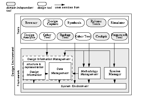
The CAD Framework Initiative suggests the architecture shown in Figure 3 as the reference architecture for a design environment [CFI-FAR 93]. According to this architecture, a design environment consists of a framework, domain independent tools and design tools. To build an environment complying with this structure, design tools have to be integrated with the framework components.
1.6 Requirements and problems


Figure 3.
CFI reference architecture for a framework-based design environment. This high-level view shows the dependencies between framework services and tools.

To summarize, in the area of electronic design we have to meet the following requirements on the management of design information, on design methodologies, and on design environments:

R1
Manage structural information about design objects

R2
Manage design objects from different domains and different levels of detail

R3
Support abstraction by distinguishing interfaces and implementations

R4
Support top-down design. Design objects may be incorporated into the composition hierarchy when only their interface but no implementation has yet been defined.

R5
Support configurations of design objects for different design tasks

R6
Support design description languages

R7
Support the integration of commercial design tools with framework components

Whereas requirements R1-R5 are a matter of an appropriate conceptual schema for design information, there is a trade-off between requirement R1 and R6/R7. The designer thinks of his design in terms of design objects. Design objects have a well-defined interface, they can be versioned, used as components in compound modules, and they can be checked for functional equivalence. Framework tools support this point of view by providing browsers and query interfaces that let the designer browse the design information according to different criteria. On the other hand, language based design tools expect design files as input and produce files as output. In general, a design file contains more than one design object, embedded in some contextual information.

A design project could adhere to the policy that design files describe only single design objects. This way, design files could serve as representatives for design objects and can be used as end-points of relationships and holder of attributes. Whereas input files can be purposefully arranged by a designer to describe only single design objects, the contents of result files are under the control of design tools and beyond the control of the designer. If there is no support from the framework, the designer has to manually analyse the contents of result files, split them at design unit borders and insert them as single files into the data management component. In addition, relationships among result design objects and between derived design objects and the originals already in the database have to be established manually. This is the necessary mode of operation in the JESSI Common Framework [JCF 94a].

In this thesis, we will describe a new framework service that helps to encapsulate design tools to avoid this tedious and error-prone manual processing. Its design is based on the three principles we will develop in Chapter 2. Following these principles, design tools are encapsulated into the framework. No access to tool source code is required. With the assumption that commercial design tools interface to design descriptions by means of file input and output, we need to extract structural information and representational information from design files on import into the design information management system and to reconstruct valid design files on export from this system. Using this approach, it is possible to use the browsing and querying facilities of existing framework tools, regardless of whether design objects have been created by tightly integrated tools or by encapsulated, file-based tools. In Chapter 7 we discuss a prototype design environment based on the new integration service that supports the VHDL language. The prototype has been implemented both on the Nelsis CAD Framework and on the object-oriented database management system ObjectStore and encapsulates some design tools from the Synopsys suite of synthesis tools [Schettler 94a].


Footnotes

(1)
This is frequently called "level of abstraction". To avoid confusion, however, we will rather use "level of detail" in the sequel.

[Table of Contents]

[Stellingen, english version]

[Top of Chapter]

[2. Integration]