[Table of Contents] |
[Acronyms] |
[Abstract, dutch version] |
[Table of Contents] |
[Acronyms] |
[Abstract, dutch version] |

|

|
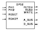
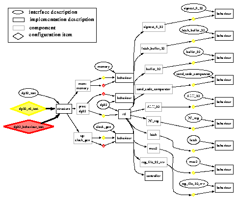
The actual microprocessor is embedded in a test bench circuit which is depicted in Figure 32. As this thesis is about CAD frameworks and not about electronic design, the detailed design description is not relevant to us. Examples taken from this description are used throughout the text to illustrate concepts. What is relevant, however, is the overall disposition of the design. Figure 33 depicts the composition hierarchy of the design description for the DP32 test bench circuit along with two configurations.
| Instruction | Name | Function |
|---|---|---|
| Br-ivnz | branch | if cond then  |
| Brq-ivnz | branch quick | if cond then  |
| Bi-ivnz | branch indexed | if cond then  |
| Biq-ivnz | branched indexed quick | if cond then  |
| Instruction | Name | Function |
|---|---|---|
| Ld | load |  |
| St | store |  |
| Ldq | load quick |  |
| Stq | store quick |  |
| Instruction | Name | Function |
|---|---|---|
| Add | add |  |
| Sub | subtract |  |
| Mul | multiply |  |
| Div | divide |  |
| Addq | add quick |  |
| Subq | subtract quick |  |
| Mulq | multiply quick |  |
| Divq | divide quick |  |
| Land | logical and |  |
| Lor | logical or |  |
| Lxor | logical exclusive or |  |
| Lmask | logical mask |  |

|
[Table of Contents] |
[Acronyms] |
[Top of Chapter] |
[Abstract, dutch version] |